Flocking Behaviour Simulations
This post details my journey learning about flocking behaviours, the mathematical models behind them, and my own implementation using WebGL. You can also see the final product before you read it if you want!
I’ve always been fascinated by flocks of birds flying in the sky creating patterns like the ones you can see in this video:
Reference material for my end goal
And as usual I’ve thought, how hard can it be to recreate? So off we go into the next learning adventure!
State of the Art: Boid, Vicsek, Three-Circle, Social force…
There is tons of research into this topic already, which is great because it should make the work a lot simpler! Ideally I can focus on rendering enough points in the screen to achieve a visual effect similar to the video above. I might try each of the models to see how they look and feel, or at least the ones that don’t require a ton of work to implement.
The first paper that I could find on flocking modelling was publised by Craig Reynolds in 1986 with a fairly simple model based on three rules that seem to have become “the standard”: Alignment-Cohesion-Separation.
Reynolds called each particle in the simulation a boid (bird-oid object), so I’ll use that term throughout this post and in my code. His three rules mean that when the boids are far from each other they’ll fly towards other boids. When they’re close they’ll follow each other’s directions, and if they get too close they’ll separate.
So I set out to implement this and see how it looks!
First Iteration: Reynolds’ Boids
To keep things simple initially, I decided to simulate it in 2D, make the speed of the boids fixed and have the rules determine their flight direction only (the algorithm is detailed below the visualization).
Although my end goal is to generate a visualization that looks like the reference video, so I’ll eventually need to go 3D and a few thousand boids.
My initial algorithm is:
- For each boid \( z_i \) find all neighbours \( z_{ij} \) within each of the radii (cohesion \( z_{ij_c} \) , alignment \( z_{ij_a} \) , and separation \( z_{ij_s} \) )
- For each group of neighbours \( z_{ij_k} \) calculate the center of mass \( C_k = z_i - z_{ij_k} \) and the angle between it and each boid: \( \theta_k = atan2(\dfrac{z_i}{C_k}) \)
- Update the boid’s direction \( \theta_i(t+1) = \theta_i(t) + c_k(\theta_k - \theta_i) \) where \( c_k \) is the coefficient for that rule.
Below I have embedded a CodePen with the code I have at this stage: (Green indicates that a boid is aligned to others. The mouse behaves like a predator, so boids will try to avoid it and turn red while doing so)
Basic version of Reynolds' algorithm - Codepen
The algorithm clearly doesn’t work that well yet, unsurprisingly since I’ve made a lot of simplifications to Reynold’s rules in order to quickly get something done that I can play with - but the good thing is that now I have the project setup (WebGL renderer setup, 2D boids arranged, turning of the sprites as they fly… ) so I can iterate fast and break things.
At least there is some flocking behaviour though. I can clearly see the effects of cohesion, alignment, and separation so it’s not a bad start!
Alhough I need a better way to see what the boids are doing, something that will give me an idea of what’s happening over time in case there are other obvious problems with the algorithm, so I modified the code slightly to also render a heatmap based on the boids locations:
Heat map of the boids' locations over time. If it doesn't look much like a heatmap it's probably because most boids are 'stuck' in the corners or edges (explained below), and the heatmap scales the rest to the 'hottest' value. - Codepen
If you just see a black screen refresh the page to see it when it starts!
Thanks to the heatmap I can quickly identify a big issue with my simulation: I’ve made the boids wrap around the edges of the simulation window as if it were a projected sphere. But boids on the opposite side are not currently taken into account for the distance when finding neighbours, meaning that the algorithm breaks near the edges of the simulation. Before I improve the algorithm I’d like to fix that problem so that I get accurate visual feedback.
The heatmap doesn’t look the same in the small size above so I made a video of a sped-up version where it’s easier to spot the current patterns that the algorithm produces: (make sure to select the highest quality possible to appreciate the details)
Time-lapse of the heatmap in action, making certain patterns even more obvious
The heatmap was useful because it allowed me to see patterns that weren’t obvious at first, specially with the sped up version in the video above. I find that a visualization is only useful when it gives the existing data a new dimension of information.
In this case it allows us to see patterns over time, but it doesn’t contain information about what’s going on. For that I’m going to have to rewrite the system so that it allows me to easily overlay debug information.
When coding traditional systems we debug either with a debugger, or by printing statements to a console. When working with animations like these though this is not useful, because I want to see live values as they are being updated, and sometimes not as text - I might want to see the boid field of vision as a cone for instance.
So I’m going to create a debugging system that will allow the following:
- Arbitrary lines from each boid, defined either as an endpoint, or as an angle and a distance. This will allow debugging the location of neighbours (endpoint mode), as well as cohesion/alignment (by displaying the vector it’s following, as an angle and a length).
- Arbitrary lines of text under each boid (so I can see any parameter updating live)
Below is a video of what the simulation looks like with debugging enabled:
Debugging system enabled, displaying live data under each boid, their field of vision and lines to detected neighbours
As I was working on the debugging system I did notice several bugs in the maths, mostly due to incorrect assumptions about the coordinate system and how angles were measured. I knew that positive Y is down (as is typical in computer vision - apparently due to old CRT monitors), but I had assumed that angles were measured from the X axis counter-clockwise, and they were in fact measured from the Y positive axis clockwise.
After fixing that I decided to tackle the issue with the boids getting stuck in the corners. I have two options:
- Keep the wrapping, and include boids on the other side of the window (potentially more realistic).
- Disable wrapping and instead make the boids prefer being inside of the screen with another weak force (less realistic because of the preference to be inside the screen).
For the first approach I would have to calculate the distance to each neighbour, but also to their “reflections”:
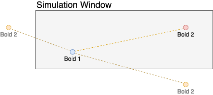
Include boids wrapping around the simulation when calculating the distance to neighbours
Unfortunately distance calculations are the most expensive part of my animation loop, so adding a bunch more is not a good solution. So I’ll make the boids “desire” being inside the screen whenever they leave and aren’t affected by any other force (so that if 3 boids leave, 2 of them following the first, only the one at the front will turn, preserving the flock).
Improvements for the Next Iteration:
- Finish implementing the Field of Vision of each boid.
- Use the distance to each neighbour when calculating their effect on a boid.
- Add the concept of desired direction to boids. Without it, they’ll just turn instantly.
Second Iteration: Boids with FoV and Non-Instant turning
Field of View
This is a pretty easy thing to implement. Each boid already has a direction of travel defined as a clockwise rotation from the global Y positive axis, so I just need to calculate the angle from each boid to its neighbours and then see if that falls within the cone of vision:
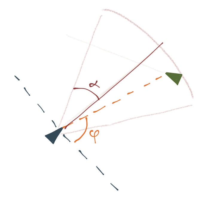
Boid vision angles and helper lines
The first step is to translate the neighbour coordinates into the reference of the current boid:
The Road ahead is being built!
I’m writing this article as I progress with my journey. Check it out every week for updates!
You can preview the “final product” on it’s Github page.
Related Posts
Building a full SaaS app in days
How I built a complete clinic management system using LLMs in a fraction of the usual time
dotdot: A social experiment
Group chat application aiming to help meet and get to know other people
Procedural Map Generation
JavaScript implementation using simplex noise and WebGL rendering
Using the latest front-end tech
Sample web I've coded to get the latest front end technologies working together.